Sometimes we take for granted the complexity involved with
the transmission/distribution of electricity from the source to the light bulb
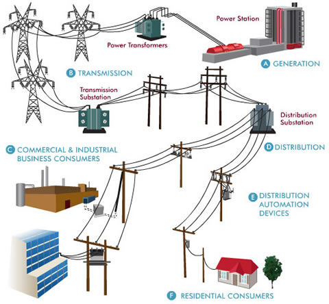
that lights up your room at night. In this blog post I will talk about the
power grid and the various components involved in the network.
1)
The power plant uses an energy source (natural
gas, oil, hydro, coal, nuclear, etc.…) as a fuel that is burned. Through the use of a heat exchanger, the fuel
heats up a liquid (water) enough to turn it into steam. This steam provides
enough heat/velocity to spin a turbine. This turbine is attached to a shaft
which is attached to a generator. The generator converts mechanical energy into
electrical energy. The electricity comes out of the generator as a low voltage
Alternating Current (AC). It’s AC as opposed to DC since the generator always
generates AC (also a transformer can only accept AC). The current also comes
out of the power plant as 3 phases. This means that each phase is 120 degrees
offset from the other. The advantage with 3 phases is that you typically always
have one of the sine waves hitting the peak at any given moment. Thus, you have
a dependable power source especially when you are using electrical equipment
that requires an almost maximum power output at a constant rate.
2)
The current then passes through a transformer to
boost that voltage to around 500,000 Volts. The reason for this is because
transmission at high voltage is more efficient and results in less losses than
at low voltage
3)
The voltage coming out of the transformer is
then sent to high voltage transmission lines and sent towards cities/customers
that will use that power. The maximum transmission line distance is around 300
miles. There are 3 horizontal lines (1 for each phase) and a ground line. At
each utility pole you can also see a vertical ground wire that goes from the
ground wire to the ground. This ground wire is then buried around 6-10 feet
below ground. You may also see a vertical metal rod at the top of each transmission
tower. The purpose of these rods is to attract lightning and send it through a
ground wire to ground as a safety measure.
4)
The voltage from the transmission line is then
sent to a transformer where it is stepped down to around 7500 – 10000 Volts.
5)
After the transformer, the voltage goes through
a bus, which is essentially a current divider. Thus you may have one of the
output legs of the bus that is rated at 7500 V while another output leg at
10000 V.
6)
The voltages are then sent through distribution
lines. At various intervals of the distribution lines are regulator banks.
These are located either in the air or underground. They regulate the voltage
along the line. Again these lines have 4 smaller lines: 3 phases and 1 ground
wire. There is also a vertical ground wire on each distribution pole.
7)
On the distribution poles are taps, which divert
the electricity to individual areas. These taps are used when an area only
needs 2 phases (or 1 phase). Thus you end up having 2 phase wires (or 1 phase
wire) that get branched off and diverted. Residential homes typically only need
1 phase current.
8)
Before the current reaches a house, the current
goes through a transformer drum. This transformer reduces the voltage from 7200
V to 240 V, which is the normal household need. 3 wires are then sent to each
house: Two 120 V wires and a ground wire. This gives the customer the ability
to either use 120 V or 240 V based off the electrical application.
9)
Finally the current goes through a circuit
breaker panel located somewhere in your home. This is where all the electrical
appliances in your home are supplied.
There are typically 10-20 different switches in the panel. A normal size
switch = 120 V (computers, lights, TV…) while a double size switch = 240 V
(dryer, washer…). At the top of the panel is the main circuit breaker switch,
which cuts all power to the panel when needed.
The switches in the panel work kind of like a fuse.
If the switch senses a connection between power and ground (current overload),
then it turns off. You then need to manually turn the switch back on after you
have reduced the current draw on that switch (unplugging appliances that are
causing too much current draw). The one advantage with the switch as opposed to
a fuse is that a switch is reusable while a fuse is not.
This is
similar to a ground fault circuit interrupter (GFCI). The GFCI is oftentimes located
on the outlet near areas with water. It contains a sensor that constantly
monitors the power difference between the neutral and the hot. If there is more
current coming out of the hot than returning to the neutral then that current
is going somewhere. Either it turns to heat or it is trying to go to ground
(through your body = shock!). Once the current difference between hot and
neutral = 5 mA, the power to the appliance gets cut off.

No comments:
Post a Comment